

All Products
-
Rotary Slip Ring
-
Capsule Slip Ring
-
Signal Slip Rings
-
Fiber Optic Rotary Joint
-
High Frequency Slip Rings
-
Through Hole Slip Ring
-
Separate Slip Ring
-
Pancake Slip Ring
-
High Current Slip Rings
-
Slip Ring Components
-
Non Mercury Slip Ring
-
Pneumatic Hydraulic Rotary Joints
-
Integrated Slip Ring
-
Slip Ring Solutions
-
 WilliamJINPAT Slip ring appearance is good, packing carefully, service enthusiasm, need to come again
 -
MartinFast delivery, good performance and good quality, looking forward to the next cooperation.
Contact Person :
John
Phone Number :
+86 1346 401 9643
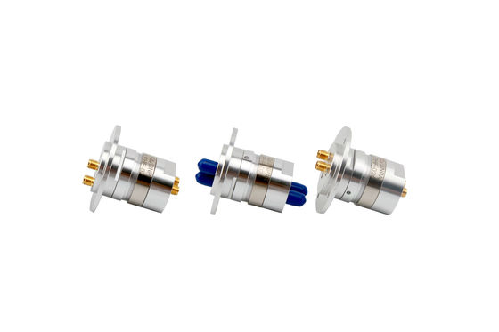
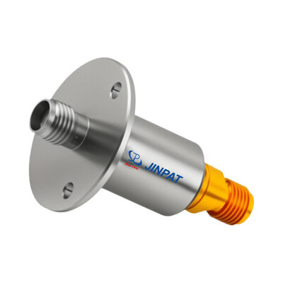
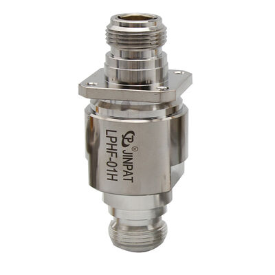
Single Channel Slip Ring Rotary Joint with DC to 18 GHz Frequency Range and Stainless Steel Case


Product Details
| Frequency Range | DC To 18 GHz | Peak Power, Max | 1500 W @ 1 GHz |
|---|---|---|---|
| Phase WOW (degrees Max) | 1° | Insertion Loss ,WOW | 0.04 DB |
| IP Protection Level | IP 60 Per EN 60529 | Case Material | Stainless Steel |
| Material Contact | Beryllium Copper | Application | Vehicle Turrets |
| Highlight | slip ring rotary joint,coax rotary joint,Single Channel Slip Ring |
||
Product Description
Single Channel Slip Ring/Rotary Joint DC to 18 GHz
Lightweight Design with Beryllium Copper Contacts
RF Coaxial Connectors are essential components installed on cables or instruments to establish or break electrical connections in transmission lines. As mechanical and electrical integration products, they provide an economical and readily available solution for compact through-bore configurations.
Ideal Applications
- Video systems (CCTV surveillance)
- Robotics and automation equipment
- Cable reels and winding systems
- Medical diagnostic equipment
- Packaging machinery
Radio Frequency Specifications
| Parameter | Specification |
|---|---|
| Interface Type | SMA Female (50 ohms) |
| Style | I type |
| Frequency Range | DC to 18 GHz |
| Peak Power, Maximum | 1500 W @ 1 GHz |
| Average Power, Maximum | 200 W @ 1 GHz 70 W @ 12 GHz 50 W @ 18 GHz |
| VSWR, Maximum | 1.20 @ 0 to 6 GHz 1.25 @ 6 to 12 GHz 1.30 @ 12 to 18 GHz |
| VSWR WOW | 0.03 |
| Insertion Loss, Maximum | 0.25 dB @ 0 to 6 GHz 0.30 dB @ 6 to 12 GHz 0.40 dB @ 12 to 18 GHz |
| Insertion Loss WOW | 0.04 dB |
| Phase WOW (degrees maximum) | 1° |
Mechanical and Environmental Specifications
| Parameter | Specification |
|---|---|
| Maximum Rotating Speed | 100 rpm |
| Minimum Life Expectancy | 5 * 10⁶ revolutions |
| Starting Torque | 1 Ncm maximum |
| Continuous Rotational Torque | 1 Ncm maximum |
| Maximum Axial Load on Interface | ±5 N |
| Maximum Radial Load on Interface | ±5 N |
| Case Material | Stainless Steel |
| Contact Material | Beryllium Copper |
| Approximate Weight | 11.5 g |
| Marking | Adhesive Label |
| Operating Temperature Range | -40 to +70℃ |
| Storage Temperature Range | -50 to +70℃ |
| Maximum Operating Humidity (Non-condensing) | 85% |
| Maximum Storage Humidity | 95% |
| IP Protection Level | IP 60 per EN 60529 |
Product Documentation
Outline Drawing - Mechanical Specifications
Application Example - Real-world Implementation
Ratings & Review
Recommended Products
Overall Rating
Rating Snapshot
The following is the distribution of all ratingsAll Reviews